Monday, May 17, 2010

A Hunk of Mahogany -- AKA the Transom

Finally, time to blog—this weeks exciting episode is about the transom. Our transom started life as a piece of rough sawn 4/4 African Mahogany 10” wide and 16’ long. After planning our board was reduced to ~7/8” and was cut into 2 pieces each about 44” long. The two pieces were then matched together to get the best looking grain with the hope that it would look like a single board once we glued it up.


The process we used is as follows:

• Joint the edges of the two boards

• Position and use the router to place 4 biscuits (extra strength)

• Dry fit to ensure that everything is right (expand the size of a couple biscuit slots because they are too small)

• Mix and apply epoxy

• Slather biscuits with epoxy and slide them into one side of the board

• Apply epoxy to the rest of the board edge

• Push the boards together and gently lay them down on the top of the table saw (with wax paper under the joint)

• Clamp the boards to each other and also down to the table saw top (nice and flat)

• Wait

Once the epoxy was dry we unclamped it and had the good fortune to take it to my son’s shop class to run it through a brand new General thickness sander. Tam, if you are following along on our blog, thanks again for this kindness, it really saved us a bunch of time and the end result was far superior to anything we could have done with our tools.

Here is a picture of the end product. Can you see the line? Or is it one board?


Now the real fun gets started. Willy calls for a top curve on the transom, but the plans do not show the radius of this curve only that the center will be 2” higher than the side height. Scaling the curve of the plans showed a radius of 84” so I knew that a large trammel would be in order. Working with scrap pieces of plywood for the trammel I gradually worked my way up to a radius of ~120” before the center was 2 ¼” higher than the middle and that is where I decided to stop the madness.

Hereare the pictures of the trammel jig for my router.


I cut a pattern in a piece of MDF and then used that to cut the actual transom. I decided that the two step method was safer than directly cutting the transom on the trammel since I do not have enough mahogany to make another transom with should I accidentally wreck this one.


The transom is a complex board with many angles that have to be cut.  On Willy the transom is slightly angled backwards from the stem of the boat and of course it is significantly wider at the top than the bottom.  All of which means that the sides of the transom are complex angles (up and down--height,  and front to back--thickness).  To determine these angle we went back to the lofted plan to determine the side angles and to the plans to get the front to back angle. 

Using the table saw the blade was set at the correct angle 10 degrees, and the transom was held down on the sliding table at an angle.  Lots of care needs to be taken at this step or you will end up with one of the beveled angles going the wrong way.  I wish I had taken a picture at this stage to help you visualize.

Cut the board without problems and then trial fit it to the boat.  It was clear that the front to back angle was wrong, thankfully we could just remove more material.  So back to the table saw, change the angle ( a bit of a guess now) and re-cut.  Whew, it all worked out.

Lots of steps to get to this point but it was nice to finish up and to screw the transom to the chines on the boat. Next up planking.

Tuesday, May 4, 2010

Lining Off

With the stem in place and a full head of steam, we are excited to be thinking about moving into the planking. But first, we have to line off the boat…a job that everyone says is more feel than science.

Willy calls for five planks and although they are drawn onto the plan on the front page we realize upon inspection that the lines shown have no reference to reality. We think that the planks will look best if they appear to all be about the same size. For the middle planks that will be no problem. But the garboard and sheer strake planks present their own issues. Optically the garboard plank will include the thickness of the flooring, so this plank needs to be a little smaller than the others to appear the same size. Whereas the sheer strake plank will be partially covered by the outwale so this plank needs to be a little bigger than the middle ones.

So there you have the theory, in reality we ended up making all the middle planks the same width, the garboard about ½” smaller and the sheer strake about ¼” bigger. As it turned out our planks are not wide enough to accommodate a sheer any wider so we compromised.

We had real problems with getting good battens for the lining out. At first we ripped up a spruce 2 x 4 in to 3/8” strips and even though the board was straight to start out with it had some incredible internal forces that warped these thin strip something fierce. For stability we decided to use plywood. The 3/8” ply was ripped into ¾” wide strips (the width of our overlap) and scarfed together to make 16’ battens. We encountered some difficulties with battens where there was a gap in the 3 ply, plywood—this was solved quickly by brad nailing a section of reinforcing plywood over the bad piece. It was amazing how visual this task really is, there is lots of looking at the battens from different angles in order to determine what a “fair line” really is. Here is was we have decided to run with:


Oh, and did I mention that we needed to plane off the chines before lining off?  Probably not so here is a short of that process using old fashioned hand tools--a delightful job actually until you get right up tight to the stem where the whole process gets a little more trying.  Simply plane until a board laid across the chines lies flat on both chines.  Here is junior at work:


Our planks were purchased off a Kijiji listing for “magogany boards”. The mahogany boards are approximately 8’ long and 5 ½” wide and were used to panel a rec room for the past 20 years or so. Willy is ~14’ long and since we couldn’t find an inexpensive board stretcher we decided to scarf the boards to get the desired lengths.

Scarfing has been a huge pain in the neck, first we built a scarfing jig for a router—basically a ramp at a 12:1 ratio. Unhappy with the resulting feathered edges of the scarf we experimented with a table saw scarfing jig. This jig worked really well for the narrow chines but it is limited by the height of the blade to about 2 ½”. I tried to come up with a fool-proof way to run the board through a 2nd time to get the other half of the cut but eventually decided to wasn’t very repeatable or accurate. So I went back to the router jig and played around until I started getting nice square looking edges on the scarfs.


Router Scarfing Jig Tricks

1. As the wood gets thinner and thinner it has a tendency to start to lift up at the leading edge. Clamping it more aggressively will not stop this from happening. The result is a ragged leading edge if you just continue to finish the scarf. The trick is to elevate the back end of the board, this will keep downward pressure on the leading edge so that you can get a nice square finished edge.

2. Slowly advance the board along the scarfing jig taking medium depth passes at the beginning and lighter passes as you get close to finishing up.

3. Draw a line across the jig base to indicate the intersection between the base and the router bit. By doing this you will finish all of your scarfs in the same position and of course know when to stop (note: if you move the board beyond this point you will probably get a ragged edge cut again).

4. Another advantage of elevating the back end of the board is that you don’t need to clamp the board into position—instead I just used a small anvil as a weight to secure the board and had no troubles with the board moving during routering. Tip – check the location of the anvil by looking at the front edge of the plank, if it is too far back the leading edge of the plank will start to rise up off the base of the jig.


Using this method I found that scarfing can be a very rewarding and easy task with highly repeatable results. Although I will continue to use the table saw jig for smaller pieces of wood as it is much quicker and yields excellent results.

Gluing up the scarfed boards has been a long process that has been dictated by the speed at which our epoxy hardens. We purchased Industrial Formulators G-2 epoxy because it will cure in colder temperatures which has been a real blessing as there have been very few days so far this year when our “boat shed” (read garage here) has been above 70 F for much time. The downside to this epoxy is that it takes a long time to set up, generally 24 hrs. Consequently we have been gluing up 3-4 boards every day for the past few days and are just now ready to start the process of planking. But first we need to finish up the transom and get it installed—stay tuned!!!


Thursday, April 22, 2010

The Journey of the Stem

Hi,

Sorry about the delay in postings. Although we endeavour to keep our followers informed, it sometimes seems like building can come to occupy blogging time. As we are tentatively planning to finish this craft by Summer, it seems as though we need every opportunity to work that we can. Anyways, significant progress has been made since the purchase of materials, and the stem is now completed.
Stem Pieces and Templates
As mentioned previously, we decided to build the stem out of three laminated mahogany layers. By doing this, we hoped to achieve the required 2.5" while still keeping weight (and costs) down. The adhesive of choice for this task was System 3's G2. Originally used to construct aircraft, and designed to have superior joint strength and flexibility, we figured that it would be ideal for the task. Anything that can be trusted to keep a plane in the air is definitely good enough for a little knockabout sailboat. In addition, this stuff has incredible open time--it will remain workable for up to 4 hours after preparation! This is extremely useful when one needs to glue several joints (eg all of the scarfs for the planking), as it does not place pressure on expedience, which ultimately leads to mistakes. Because Atkin specifies a 2-piece stem in the drawings, we had a total of 6 pieces to cut out and keep track of. After roughing components to size with a jigsaw and finishing with a router and template, we epoxied them to form the finished stem. A 2.5" thick stem is truly formidable when completed! As the mahogany we selected is fairly hard, we are confident that the stem will handle any abuse it might face. Another step in the journey of building a boat!

Glue-up of the Stem

The next challenge was that of the stem rabbet--a daunting task to first time builders, as a mistake here can tarnish a beautiful piece of wood. Problematically, the plans do not illustrate the rear delineation of the rabbet-the bearding line. Although we had a general idea of the position of the stem line (the front boundary of the rabbet), the bearding line was a bit of a mystery. However, after some puzzling over the plans and reading others' accounts of this step, we found that, in fact, the process used to determine this line is fairly straightforward. From the overhead view of the craft in the plans, which defines the angle at which the planking meets the stem, it is possible to use trig to complete the calculation. Knowing the width of the planking and the angle, one can find the hypoteneuse (the distance between the bearding and stem lines) at both the top and bottom of the craft. From here, a batten between the lines lends the shape the rabbet must take. For a more in depth account of this process, I highly reccommend the Unlikely Boatbuilder's blog. Finally, our preparations for the build have paid off! Using a mallet, a few sharp chisels and a fid (a small piece of wood the same dimensions as the planking), the stem rabbet can be cut. I know that it's frustrating that all the books leave it at this, but it is a process that is much easier to experience than to explain. Being sure to make careful, conservative cuts and checking progress with the fid often will ensure a tight fitting rabbet. It truly is not as difficult as it may seem.

Rivets and Roves for the Hull
316 Stainless--Pricey Stuff!
Lastly, while on vacation, we obtained our required hardware from Jamestown. With this and a completed stem, there is little that still stands between us and planking. Dauntless, we shall press forward into the realm of spiling battens, lap bevels, gains, and much more.

JoeLapstrake   

Monday, April 12, 2010

Spinning my Wheels

The frames are built, the strongback is assembled, the chines are 80% done, and now I need a bunch of things to move forward. 

First on the list is wood for the stem and transom.  The plans call for white oak for the stem and mahogany for the transom.  The stem is 2 1/4" wide, or 10/4 material....a look at the local hardwood vendors proves to be fruitless for anything that thick as a single piece, some guys have some 8/4 but that just won't do.  So the only choice is to glue up two or three pieces to get what I need, the problem is that oak is not a good candidate for gluing with expoxy because of the high tannins levels.  This leads to a long investigation into the merits of the various glues that are appropriate for below the water line useage.  Turns out that the choices are limited to epoxy and resorcinol. 

Resorcinol is the glue that is used to make marine grade plywood and what everyone complains about is the dark glue that it leaves and the fact that it is not a gap filling glue, in fact the surfaces need to be well-mated and clamped for the glue to do its stuff.  On the positive side it can be used with oak and no one has any horror stories to tell about failing joints--even after 20 years.

Okay I'm in, resorcinol it is then.  Here comes the spinning my wheels part...turns out that resorcinol is not easily available around here so now I'm back to square one.  But a little more knowledgable on glue!

Decided to try out a local hardwood wholesaler called PJ White that I had heard will sell retail also.  Turned out to be a good move, as I was pulling up to the yard I see a guy driving a fork lift with 8-10pcs of mahogany out to a contractor's truck.  Beautiful looking boards all between 10 & 14" wide, 4/4 material each board 16' long.   They carry two types of mahogany, african and honduras, african is about 1/2 the price of honduras.  Ended up buying a single 11" wide plank, 16' long with nice figure (thought it will look nice if left bright on the stern of Willy) that I cut in two with a handsaw in the yard before loading it into my Volvo wagon.

The 4/4 material turned out to be closer to 5/4 so my plan is to plane a little off one side, glue them together with epoxy and use one of the 8' mahogany boards for the stem.  I will have to find a use for the remainder of this board.  But, the price was so good from PJ's that I can't go wrong--about 30% cheaper than the other local suppliers.

Feeling pretty good about getting the wood and glue issues all resolved but then started thinking about that mahogany and wondering what the moisture content of that wood might be???  Don't have a moisture meter so I am a little resistant to start cutting it to size and thickness right away.  Besides, there are still more problems that I need to solve before I can go much further.

First on the list is to order fasteners.  The original plan was to use copper nails and burrs and silicone bronze screws.  Jamestown Distributors was the vendor of choice (seem to have the best prices) but when we went to place our order we discovered that the price of silicone bronze screws went up 80% (we were stunned!!!). 

This led to a massive internet search on the pros and cons of using either bronze or stainless steel.  Both seem to have there place in wooden boat building but the clincher for us was a post by a boat builder on Vancouver Island who was replacing the hull on his boat that spent the last 15 years in salt water and said that the stainless steel screws he was removing were all in excellent shape.  That is more than enough proof for us prairie boys that only have some fleeting hopes that our boat will get into the salt off Vancouver Island some year.

I also changed my mind and decided to use roves instead of burrs.  The nails for the roves are smaller in diameter than the nails I would have to use with the burrs and since our planking is 3/8" I was concerned that the larger holes would impact the structural integrity of the plank edges.

With all this time on my hands I decided to would be a good idea to mock up the stem and see if we really understand how to create the rabbet.  So we took a piece of spruce 2x10 and laid out the stem from our lofted pattern.  Really quite simple, we drew the stem up on a piece of 1/4" ply so we just put some nails through the key points along the perimeter and then using a batten re-drew the stem on the 2 by.  

Once we had the rabbet line and the bearding line (following the instructions from the "Boat Builders Apprentice") in place we made a fid (a fancy name for a piece of wood the same dimensions as your planking) we starting working away at chipping out the rabbet with our chisels.  

When we put the stem into place we were pleased and a little surprised to see that our rabbet was good ( a little rough but passable).  

All that chipping with a hammer led to another project--making a proper wooden mallet.  Found a great plan by Diego de Assis that provides all the proper dimensions --http://www.wkfinetools.com/contrib/dAssis/art/mallet/mallet-1.asp

I made mine from some scrap maple and consequently built the head up out of 3 layers rather than the single piece that Diego uses.  If you decide to build yours this way here are a couple of pointers that will save you some head scratching.  

1. Use an adjustable square to set the angle of the handle and the insides of the center mallet head pieces.  Once you set this angle you can easily lay out all these pieces and then cut them.
2. Glue up the head in sections, position and glue center head pieces (2) to one of the side pieces and let it cure.  Then glue the other outside piece in place. It is much easier to build it up in phases rather than dealing with a slimey, moving mess of all 4 pieces at once.

So far I have been really impressed with how well this tool works.  At first I thought the angle on the head might we too much but after using it for a while I can tell you it is perfect!

Joe 

Tuesday, March 23, 2010

How to put a clamp on things

Clamps are an essential part of any boatwright's arsenal. They find countless uses around the shop and are downright indispensable when laying laps. However, it always seems like one needs just a few more than he/she has. The boatwright is then faced with a question: "How shall I obtain more?". There are two options: buy some or build some. Unfortunately, the former is usually quite a costly affair, as clamps run anywhere from $7-$25 apiece. When you need to place one every foot on a 14' boat, it puts quite a dent in the project funding. Because of this, many people (including us) turn to the latter approach. Some design very elaborate bandsawn clamps, but, in our experience, it is much easier (and faster) to use a simpler approach. Using the method outlined below, it is possible to turn out clamps for under $2.50 each.

Firstly, it is important to determine what depth of reach is required. As we will be using 6" lap material, our clamps must have a deep throat. A 12" piece of 2x2 fits the bill perfectly. For pads, we used 1/4" material for the front part of the clamps, and 3/4" for the backs (ensure that the difference between widths is at least the same width as the joint to be clamped--otherwise the clamps will skew, reducing holding power). For hardware, we recommend 4-6" carriage bolts and 3-wing poly handles (available from Lee Valley). The plastic handles provide much more leverage than a wing nut, not to mention a lot more comfort. The photographs below should make it easy to copy our method


All of the parts for one clamp cut out (mise en place, as the French would call it). The 5/16" hardware ensures sturdiness.

After drilling a hole in each of the clamp halves, thread the bolt through...
Et voila, un clamp!

Hope that this tutorial helps to clear up any confusion surrounding the creation of clamps (and keeps a few hundred $ out of the hands of those Jorgenson guys :)

Joe Lap

Thursday, March 11, 2010

Strongback - Adding the Transom Support

Today's boat building activities consisted of adding the transom support to the strongback and sharpening plane blades for the job ahead.

I am sure that professional boat builders have a method of attaching the transom to the strongback without driving a fastener through the transom that would have to be plugged later.  We were unable to figure out that method from either our readings or from the internet so we have elected to add a plywood sub-transom (a new boating term no doubt!!)  frame to which we can clamp the real transom.  To do this, we first attached a couple of sister joists to our strongback with the appropriate angle cut in them for the transom (Picture 1).  The plywood sub-transom was leveled and screwed to the sister joists (Picture 2).  

Sharpening is an art form from simpler times when tradesman used hand tools--chisels and planes to fashion wood.  Traditionally these tools were sharpened on oiled stones in the West (North America and Europe)and water stones in the East (Asia).  It wasn't until recently that I learned how to really get my tools sharp from my son who learned from his woodworking shop teacher.  Here is the process I now use;

1. Use an electric wet stone to put a concave 25 degree bevel evenly across the whole blade.  Even though this may sound hard it really isn't, you establish the angle between the tool rest and the wheel and then slowly move the blade across the stone (I find it is easier if the stone turns towards me).  You can see your progress and the evenness of your cut after each pass and you adjust accordingly until you have ground the blade all the way up to the tip.

2. Turn the electric wet stone off and clean off the blade.  Now you need to put a micro bevel on the blade.  To do this I use adhesive backed silicon carbide 3M micro-abrasives (sandpaper) from Lee Valley Tools that I have attached to a flat piece of plate glass.  It is easiest to use a jig to hold the blade but if you don't have one you can still apply the micro bevel by hand.  All you do is increase the angle on the blade slightly and make several passes back and forth on the sandpaper until it is super sharp.  I generally start with 15 micron and then finish up with 5 micron.  

3. Go cut some wood by hand and enjoy the satisfaction of a sharp blade and the silence of non-electric motor cutting.

I sharpened blades for a block plane and an ancient jack plane today using this method and both planes will now cut long thin curls in both red oak and spruce.   

Joe Lap       


Monday, March 8, 2010

The Great Rivet Debate

It appears that everyone has their own opinion regarding the use of rivets and burrs/roves on a lapstrake craft. Although there is a general consensus that rivets are the go-to fastener for laps, that is where the agreement ends. Here we encounter two different schools of thought: Roves or Rivets. Those who use roves argue that these conical washers compress slightly upon peening the nail, increasing tension on the joint. According to some sources, they are also more traditional on European boats. However, roves are significantly more expensive than their counterparts, and they also leave unsightly lumps on the inside of the craft. Burrs have the advantage of being more streamlined, and, if used properly, can still create a sound joint. A "tight fit" burr allows a tightening of the joint similar to, if not quite as strong as the rove. As we learned from the Woodenboat Forum, some Icelandic boatwrights traditionally use copper coins in the place of burrs. Sounds crazy, but, hey, it works! There are boats still in the water to prove it. Burrs are also much more economical than roves (although not quite as cheap as pennies). So where does this leave us? Each has to make his/her own decision. We have decided, being a little cheap, that we will use burrs. In addition to their inexpensive nature, we are looking to avoid the lumps that roves would cause on the interior of Willy. Any other comments regarding the history and/or adequacy of each of these methods are welcome.

Joe Lap

Strongback Construction

As we mentioned yesterday, the strongback has recently been completed. After taking a few photos today, we figured that we should explain the strongback in detail. We chose to go for a design that raised the molds high off the ground, as we will have to work inside the ship while riveting (and we are both over 6' tall). On a similar note, the stringers attaching the legs make a very convenient tool rest. Once the planks go on, they will also function as a seat for the man peening rivets inside the boat. This model allows the molds to sit at about chest height, a comfortable working position. The molds are 2 by construction, reinforced at the corners using ply. Although simple, they are very sturdy. The rocker in Willy's hull becomes more evident now that the strongback is assembled. The second photo illustrates the method used to connect the molds to the back--a detail overlooked in most books. It also demonstrates the technique used to fit chines at each station. A basic positioning system allows the builder to quickly square and level each mold before attaching it. Chines will be made of 3/4 x 1 1/2 red oak. The spaces for chines to run over each mold were cut using a dozuki saw and chiseled to fit the chine. That saw is perhaps one of the finest (and fastest) cutting handsaws that we have ever seen. As far as value in a general-purpose saw goes, this one can't be beat. For the woodworker, it also excels at cutting dovetails. The strongback still needs to be modified to accept the stem and stern (both yet to be built--need to find suitable material). Any suggestions regarding stem/stern material choice? The sides will lapped with 3/8" mahogany (NOT ply), but we still need material for the cross-planked bottom (tentatively 3/4" cedar). As we approach the purchase of fasteners and bedding compounds, we will focus on a few common debates regarding choices for the next few days. Photos of the strongback are below.

Joe Lap


Sunday, March 7, 2010

Introduction


Hello all;


This blog will document the building of a small wooden sailboat. As we are amateurs (this is our first boat), we hope that this will be an opportunity to share our knowledge and learn from others.

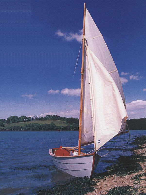
We have chosen to build John Atkin's Willy Winship, a 13' 9'' flat-bottomed sailing skiff.
We ordered the plans for Christmas from the Woodenboat Store in December and have been studying them and reading many boatbuilding books in preperation for the build. In fact, we highly recommend Greg Rossel's The Boatbuilder's Apprentice, as it is straightforward to understand and very applicable to any small boat.
Excited about the build before us and anxious to get our hands dirty, we plunged right in and began the first mold (without lofting first). First lesson: Loft First! After some frustration with the inaccuracy of the unlofted mold, we decided to loft the next four. Although we had been somewhat anxious about the lofting process by the many complex explanations outlined in some books (including using multiple sheets of ply and/or the floor of a room), we discovered that, to our delight, it was a simple and enjoyable process. All that we needed was a square, a good rule, the back of a laminate desktop, and a few pencils. Because Willy is a flattie, she has relatively simple lines. After building four of the molds to the lofted plans, we found that the process was so superior that we lofted and rebuilt the first mold.

Seeing that the weather here was so beautiful this weekend, we decided to construct our strongback--the spine on which the boat will be built. It is a rather simple affair, consisting of a couple 2x10's and the aforementioned molds, but it is rock-solid! Another word of advice: ensure that any strongback (and each mold) is level and square before moving on. After all, this is the platform on which the boat will be built--small mistakes here will translate to the finished project.

So, that's about as far as we've gotten so far. Hope to post a few photos of the set-up and any new progress soon. Any advice is welcome.


Joe Lap